Optipedia • SPIE Press books opened for your reference.
Laser Interferometer
Excerpt from Fourier-Transform Spectroscopy Instrumentation Engineering
Most commercial FT spectrometers today use HeNe-laser interferometers as position sensors. There are two types of laser interferometers: homodyne and heterodyne. A homodyne interferometer uses a single-frequency laser source, whereas a heterodyne interferometer uses a laser source with two close frequencies.
The homodyne interferometer using a HeNe laser as its source is a commonly used position sensor in FT spectrometers. It is known that with a simple Michelson setup, the moving mirror’s relative displacement can be determined by counting the sinusoidal pulses. The speed information can thus be obtained by measuring its frequency. However, in order to determine the direction of the travel (hence the position and the velocity), additional optics is needed. A typical optical layout to accomplish such tasks is shown in Fig. 1.
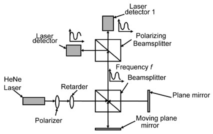
Figure 1 Homodyne-laser interferometer with quadrature detection.
A linearly polarized laser beam passes through a λ/4 retarder (a quarter-wave plate) and it becomes circularly polarized. In order for this to occur, the incoming beam’s polarization direction needs to be at 45 deg relative to the retarder’s principal axis. Circularly polarized light has orthogonal fields that are 90 deg apart in phase, for example, the x-component leading the y-component by λ/4. A polarizing beamsplitter then splits the output beam into two orthogonal fields, each sensed by a detector. As a result, depending on the direction of the mirror’s travel, detector 1 leads or lags detector 2. This phase information can then be used to deduce direction and therefore the position of the mirror. Most commercial motion-control boards contain two channel-encoder inputs that accept digital quadrature-encoder signals and automatically perform directional measurements or up and down pulse counting.
A heterodyne interferometer measures mirror displacement by measuring the phase change due to the Doppler effect, similar to the way police radar measures the speed of a car. In order to do this, however, the radiation’s temporal frequency needs to be made much smaller (remember that light’s temporal frequency is much too high to be detected with today’s detectors and electronics). This is achieved by using a source that contains two frequency components located close to each other, creating a beat phenomenon whose amplitude variation can be made much slower than the radiation frequency itself (in the order of megahertz), as illustrated in Fig. 2. The envelope frequency is given by f1 – f2, the difference of the two frequency components of the source radiation.
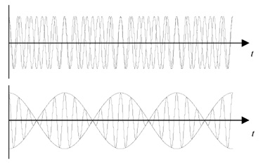
Figure 2 Beat phenomenon caused by the superposition of two monochromatic waves having two slightly different frequency components.
Figure 3 shows a simple schematic of a heterodyne interferometer configuration. The two frequency components have linear polarization, orthogonal to each other, which are then separated at the polarizing beamsplitter. The recombined radiation has a beat frequency of
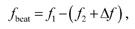
where the Δf term is due to the Doppler shift. Its polarity is dependent on the direction of the motion. This signal is then electronically “compared” with the reference signal f1 – f2 (the beat frequency corresponds to zero velocity). Readers are referred to Ref. 1 for complete mathematical treatment of the Doppler shift effects. A phase detector is then used to measure the phase between the reference and the measured signals.
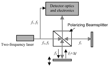
Figure 3 Simplified schematic of a heterodyne interferometer.
A few aspects of the heterodyne interferometer make it superior to the homodyne interferometer. Since the displacement information is carried on an ac signal rather than a dc signal, it is less sensitive to laser power fluctuations, ambient light, and various other noise affecting dc measurements. In addition, only a single detector is needed to measure both the displacement and the direction, thus simplifying alignment. However, it requires a highly stabilized two-frequency-laser source and more intricate detector electronics.
Reference
- A. H. Slocum, Precision Machine Design, Society of Manufacturing Engineers, Michigan, pp. 401–625 (1992).
V. Saptari, Fourier-Transform Spectroscopy Instrumentation Engineering, SPIE Press, Bellingham, WA (2003).
View SPIE terms of use.

Non-Member: $52.00