Optipedia • SPIE Press books opened for your reference.
Retroreflectors
Excerpt from Field Guide to Illumination
Retroreflector Geometry
Retroreflectors reflect incident light back toward the direction of the light source, operating over a wide range of angles of incidence. Typically they are constructed in one of two different forms, 90-deg corner cubes or high index-of-refraction transparent spheres with a reflective backing. Retroreflectors are used in transportation systems as unlighted night-time roadway and waterway markers, as well as in numerous optical systems, including lunar ranging. Some are made of relatively inexpensive plastic pieces or flexible plastic sheeting, and some are made of high-priced precision optics.
The performance of retroreflectors is characterized within a geometrical coordinate system, usually with three angles for the incident and viewing geometries and a fourth orientation angle for prismatic designs like corner cubes, which are not rotationally isotropic in their performance. All the geometric variations are described in detail in ASTM E808-01, Standard Practice for Describing Retroreflection, along with expressions for converting from one geometric system to another.
Two angles commonly used to specify the performance of retroreflectors are the entrance angle, ß, and the observation angle, α. The entrance angle is the angle between the illumination direction and the normal to the retroreflector surface. High-quality retroreflectors work over fairly wide entrance angles, up to 45-deg or more (up to 90 deg for pavement marking). The observation angle, the angle between the illumination direction and the viewing direction, is generally very small, often one degree or less.
Another useful angle for interpreting the performance of retroreflectors is the viewing angle, υ, the angle between the viewing direction and the normal to the retroreflector surface.
Retroreflector Radiometry
The performance of retroreflectors is quantified by several coefficients. These are the most common:
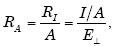
RI, coefficient of retroreflected luminous intensity,

where E┴ is the illuminance on a plane normal to the direction of illumination, and I is the intensity of the illuminated retroreflector.
RA, coefficient of retroreflection,
where A is the area of the retroreflector.
RL, coefficient of retroreflected luminance,
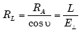
is the ratio of the luminance in the direction of observation to E┴.
Rφ, coefficient of retroreflected luminous flux:

RF, retroreflectance factor
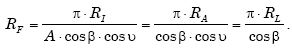
It is the retroreflectance factor, RF that is numerically equivalent to the reflectance factor, R.
Retroreflectors are often specified by the coefficient of retroreflection, RA, for various observation angles and entrance angles.
Values for RA of several hundred (cd/m2)/lux are not uncommon, corresponding to reflectance factors up to and over 1000.
A. V. Arecchi, T. Messadi, and R. J. Koshel, Field Guide to Illumination, SPIE Press, Bellingham, WA (2007).
View SPIE terms of use.
