Deformable mirrors enable a leap forward in x-ray telescope performance
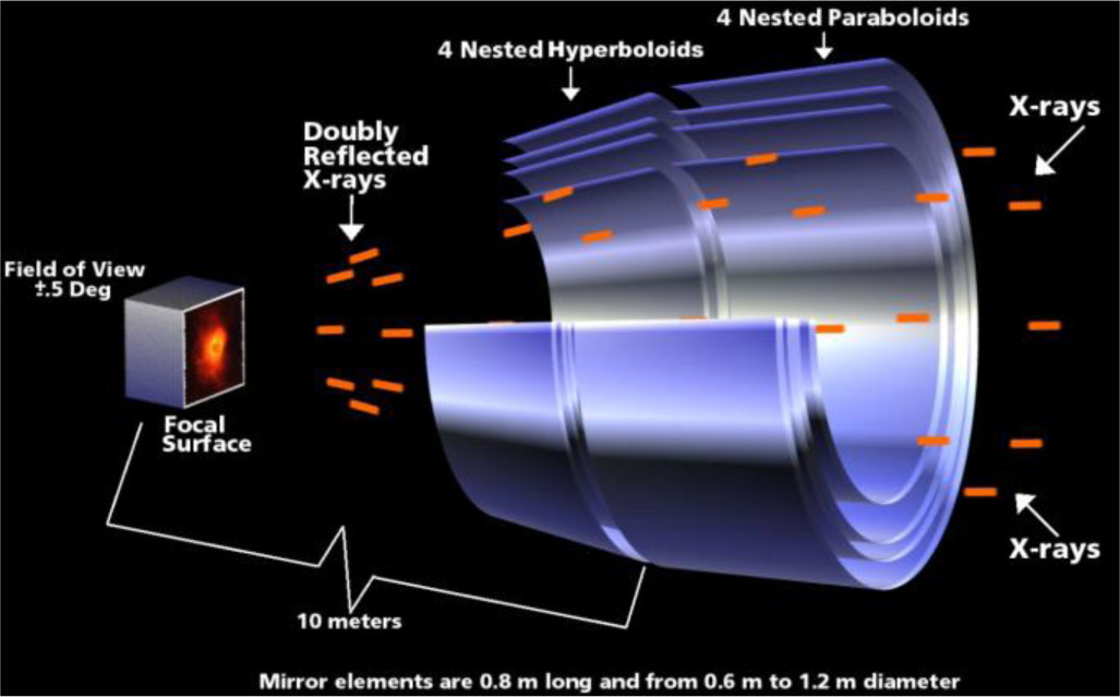
Space-based x-ray telescopes allow astronomers to study a wide range of energetic phenomena from neutron stars to diffuse million-degree gas permeating galaxy clusters. Unfortunately, x-rays are notoriously difficult to focus. To produce images, x-ray telescopes must use grazing incidence mirrors, which reflect incoming photons at very shallow angles. High-resolution x-ray mirrors usually use the Wolter Type I geometry—a double reflection off first a parabolic and then a hyperbolic surface (see Figure 1). As a consequence of the shallow angles (typically 1° or less), the collecting area is a small fraction of the mirror surface. To increase the telescope's effective area, multiple mirror pairs are nested. Thin mirrors can be nested in higher number and more densely than thicker mirrors, resulting in a large total collecting area, but they are more subject to manufacturing and mounting errors that degrade the angular resolution.
The trade-off between imaging quality and light collecting power is apparent in the most advanced current facilities. The Chandra X-ray Observatory1 employs four thick (16–23mm) mirror shells with an unparalleled angular resolution of 0.5". The X-ray Multi-Mirror Mission (XMM-Newton) telescope2 uses 58 thinner (0.5–1.1mm) nickel mirror shells with 15" angular resolution and an area-to-mass ratio seven times larger than that of Chandra. New technologies have been employed or proposed3, 4 with the aim of realizing lighter mirrors, but none are expected to achieve an imaging quality better than 5–10". We propose the use of deformable, thin, light-weight mirror segments for the Square Meter Arcsecond Resolution X-ray Telescope (SMART-X) mission concept.5, 6 SMART-X will offer image quality comparable to Chandra but with 30 times the effective area and similar, or better, cost and mass.
Our approach uses the deposition of a ∼1μm-thick film of lead zirconate titanate (PZT) piezoelectric material on the back of thermally formed glass substrates.7 The application of low DC voltage (10 volts or less) to individually addressable electrodes on the top of the PZT film generates local electric fields. These fields produce stresses in the mirror, parallel to its surface, which can correct for intrinsic figure errors and modeled contributions from, e.g., the thermal environment and the lower gravity field once in orbit. The adjustment will be performed once or infrequently, on the basis of calibration metrology data acquired on the ground. The thin-film technology offers several advantages. No heavy reaction structure is needed and the thin films have a negligible obstruction and mass penalty. Also, the sputtering deposition is scalable to larger mirrors and adaptable to different actuator geometries or substrate materials.
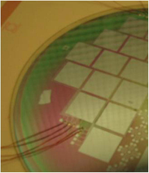
Prototypes of adjustable mirrors have been realized at The Pennsylvania State University Materials Research Insitute, depositing the PZT on glass with radio-frequency magnetron sputtering. Two platinum layers, acting as electrodes, are deposited before and after the active PZT layer. The bottom electrode is a continuous film, covering the entire substrate. A lithographic mask is used on the top electrode to obtain a pattern of independently controllable cells (see Figure 2). The deposition of large-area actuators on glass presented an early technological hurdle. The yield—the fraction of working electrodes—has increased considerably from the first samples and is now nearly 100%.8
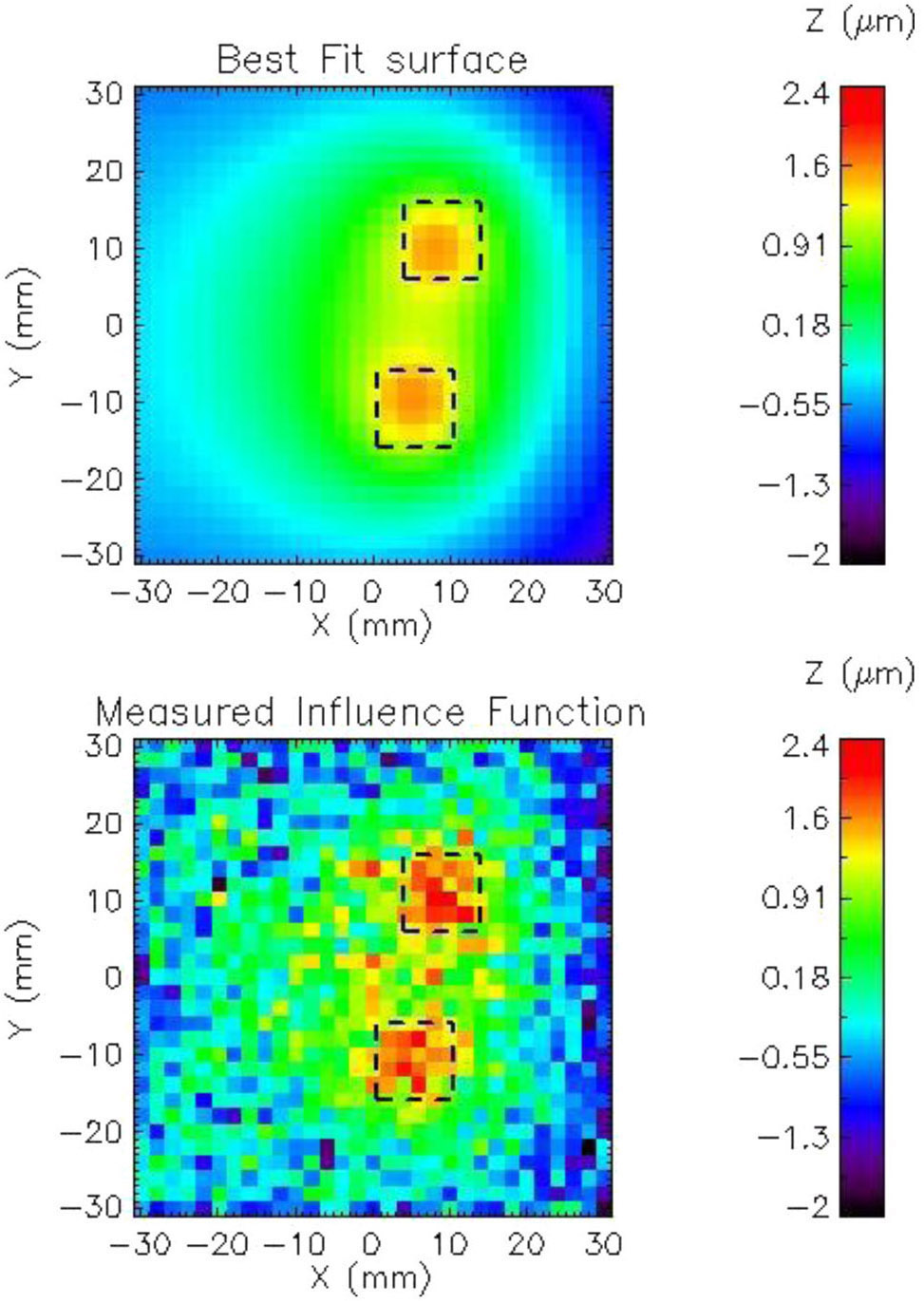
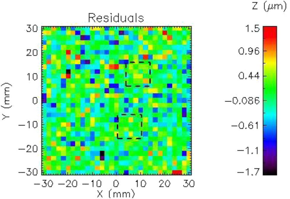
Based on finite element analysis, correction capabilities of ∼1μm are needed to deform a state-of-the-art thin mirror segment to the required optical quality.9 We performed metrology tests to verify the adjustment capabilities, validate the model, and provide feedback for the control and measurement of the surface shape.10 Figure 3 shows the measured and modeled influence functions (the difference in mirror shape as a consequence of the piezo cell activation) for two activated cells. The difference is comparable to the metrology noise (see Figure 4).
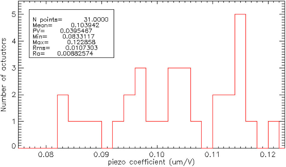
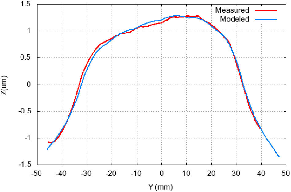
The distribution of each cell's response, in a sample with 33 active cells, is shown in Figure 5. In a real application, the desired surface shape is obtained by adjusting the voltages according to the calibration data. In Figure 6, we therefore compare the influence function profile for a row of six actuators, powered at the same voltage, with the modeled influence functions rescaled by the calibration values for each pixel.
In summary, we have proposed a new approach to produce thin, lightweight, deformable mirror segments for the NASA SMART-X telescope. We have successfully deposited working PZT films on thin glass substrates and demonstrated that the actuation capabilities are in good agreement with finite element modeling. Flat samples with yields close to 100% are routinely produced. Finally, we have recently demonstrated PZT and electrode deposition on curved, thermally formed substrates. Testing of piezoelectric cells on curved segments is just starting, while accelerated and real-time lifetime tests of actuators are ongoing. The SMART-X technology development roadmap calls for mature technology—NASA Technology Readiness Level (TRL) 6—by 2019. We therefore anticipate testing and characterizing a breadboard prototype of the adjustable mirrors with x-rays in the next three years.
This work was funded by NASA Contract NNX09AE87G, a grant from the Gordon and Betty Moore Foundation, and grants from the Smithsonian Astrophysical Observatory (SAO) and Smithsonian Institution. We also acknowledge the major contributions of our collaborators at The Pennsylvania State University Materials Research Institute, the NASA Marshall Space Flight Center, Johns Hopkins University, and SAO, without whom this work would be impossible.