External invisibility device cloaks objects at a distance
Invisibility devices commonly play a role in science-fiction scenarios. However, the recently formulated theory of transformation optics1–3 establishes a correspondence between coordinate transformations and material parameters (permeability and permittivity) that actually enables us to design invisibility cloaks that exclude electromagnetic (EM) waves in certain regions. Such invisibility cloaks can conceal an object by steering waves around an enclosed domain so that any object located inside the domain is hidden from observation. However, the hidden object will be ‘blind,’ since no outside light can reach into the cloaked domain. It would thus be desirable to design an 'external invisibility device' that leaves the concealed object out in the open so that it can ‘see’ its surroundings.4
The key idea behind our newly designed device is the concept of complementary media,5 as illustrated in Figure 1. In Figure 1(a), we present a schematic diagram of a dielectric cylinder (with radius r < a). It scatters an incident EM wave and is thus visible: see Figure 1(b). Figure 1(c, d) shows the equivalent schematic diagram and resulting (scattered) electric-field distribution for a cylindrical shell (with inner and outer radii a < r < b) composed of a specific negative refractive-index material designed on the basis of transformation optics. Figure 1(e, f) shows that when the cylinder and shell are combined, they produce no scattering and the dielectric core can therefore be made invisible by the negative refractive-index shell. However, these results can also be interpreted differently. The cylindrical shell can be regarded as optically canceling a shell of air (with inner and outer radii b < r < c) outside of it, as outlined by the dotted line in Figure 1(e). It can be proved that the domain bounded by a < r < b and b < r < c is optically equivalent to a space that is optically void. This means that light does not change phase when it passes through the domain a < r < c. However, to make a region invisible it must optically behave like air. Since an optical void is not the same as air, we need to compensate for the missing phase change that would have occurred if light passed through an equivalent volume of air. This is achieved by the dielectric-core (green) region, which acts as a ‘phase compensator.’ The exact values of the permittivity and permeability can be obtained using transformation optics.4

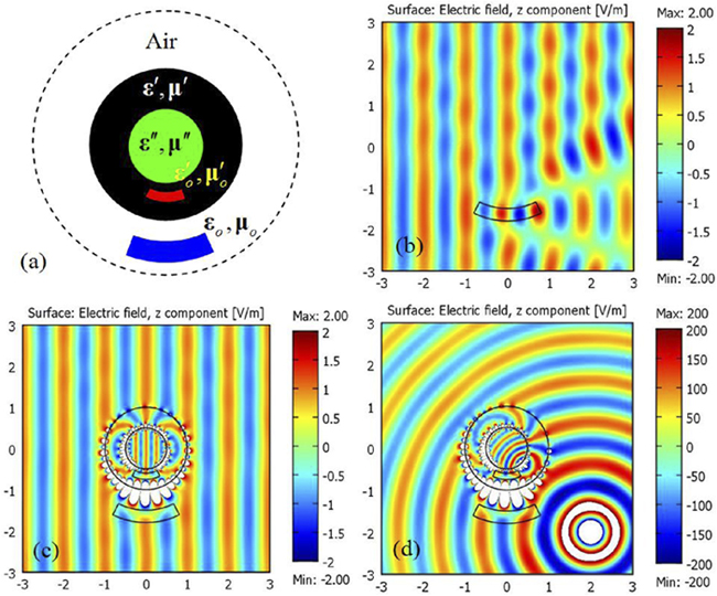
What happens if there are objects in the air region bounded by b < r < c? A negative refractive-index shell bounded by a < r < b can be designed to optically cancel the entire region b < r < c, even if it contains a foreign object. We can prove that the latter can be optically canceled by an ‘anti-object’ with permittivity and permeability prescribed by mathematical mapping (see Figure 2). Figure 2(a) represents an object (blue) that we want to make invisible. The external invisibility device comprises a dielectric core (green), a negative refractive-index shell (black), and an embedded anti-object (red) designed to cancel the optical effects due to the blue object. Figure 2(b) shows the scattering of the object when it is illuminated by an incident plane wave, while Figure 2(c) proves that the scattering is canceled exactly by the invisibility device. The entire system, including the outer air layer containing the object and the invisibility device, does not cause any EM-wave scattering and is thus invisible. We emphasize that there is no shape or size constraint on the cloaked object, as long as it fits into the region b<r<c. Multiple objects can be cloaked. The invisibility device does not enclose the object, and it meets the requirement of external cloaking. Figure 2(d) shows that the invisibility effect also works for a line source. In fact, the system is invisible to any form of external illumination. Figure 3 shows that the external invisibility device can be designed to optically cancel only part of an object.

In summary, we have designed a passive invisibility device (i.e., requiring no external power) that can make an object outside its domain invisible. The disadvantage of such an external invisibility device is that we need to custom design the device to hide a particular object. It would be more desirable if the device could conceal any object without prior knowledge of its shape. This will be our next challenge, but it seems highly unlikely that a passive device can meet these requirements.


