Optipedia • SPIE Press books opened for your reference.
Explanation of a ball lens from SPIE Press
Excerpt from Optical Design Fundamentals for Infrared Systems, Second Edition
A sphere or ball performs surprisingly well as a lens. At closer scrutiny, one finds that such an element can be broken down into two plano-convex lenses, separated by a plane-parallel plate. The positive lenses have under-corrected spherical aberration and the plane-parallel plate is over-corrected. Therefore, there is a compensating effect. A ball lens finds its main application as a coupling element for optical fibers. It deserves an analysis, especially since there are certain limitations that need to be understood.
The figure below indicates that the focal length is measured from the center of the sphere, where the extensions of the entering and exiting rays meet. This means that the back focal distance bfl is merely the difference between the focal length and the radius R of the sphere. One can see immediately that the focus falls on the rear surface of the sphere if f = R.

Ray trace through a ball lens.
The focal length of the ball lens is

Its back focal length or back focal distance is, as already indicated,
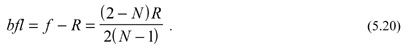
One can see that bfl = 0 if N = 2. That means a ball lens is not suitable for most IR materials, such as silicon, germanium, zinc sulfide, or zinc selenide, whose index of refraction are larger than 2. Sapphire with N = 1.6753 at 4 μm is an exception.
M. Riedl, Optical Design Fundamentals for Infrared Systems, Second Edition, SPIE Press, Bellingham, WA (2001).
View SPIE terms of use.

Non-Member: $58.00