Optipedia • SPIE Press books opened for your reference.
Magnifier, or Loupe
Excerpt from Optical Engineering Fundamentals, Second Edition
A magnifying glass (or loupe, from Old French, meaning an imperfect gem), is the simplest of optical instruments intended for the enhancement of visual capability. It is a device frequently associated with jewelers, usually taking the form of a simple positive lens. In use, the magnifier is held close to the eye, while the object to be viewed is brought to the focal point of the lens.
The average young and healthy human eye is capable of focusing from infinity, down to a minimum distance of about 250 mm (10 in.). This same average eye is capable of resolving a repeating high-contrast target with equal width black and white lines when each line subtends an angle of 1 arcmin or more. Most often, when viewing an object it is our intent to distinguish as much detail on that object as is possible. To that end we first bring the object as close as possible to the eye. When that closest distance is 250 mm, the smallest resolved element on the object—a detail that subtends an angle of one minute (tanθ = 0.0003)—will have an actual size of 250 mm × 0.0003 mm = 0.075 mm. If this resolved element is a part of a repeating pattern of equal-thickness parallel black and white lines, then each cycle (one black plus one white line) will have a thickness of 0.150 mm. The frequency of this finest resolvable pattern will then be 1/0.150 mm = 6.67 cycles/mm.
A magnifier is any positive lens with a focal length of less than 250 mm. The approximate magnification M provided by the lens is calculated by dividing its focal length into 250. For example, a 50-mm lens will provide a magnification of M = 250/50 = 5×. This formula applies to the case where the object is placed at the focal plane of the magnifier lens and the virtual image being viewed appears at infinity. This condition allows comfortable viewing with the relaxed eye. If the object is moved just a bit closer to the lens so that the image is formed at the closest possible viewing point, a distance of 250 mm from the eye, then the magnification factor will be increased by an additional 1×.
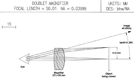
These magnification formulas relate to a thin lens with that lens placed very close to the eye, both of which are hypothetical assumptions. Due to the ready availability of optical design software, it has become a relatively simple matter to analyze a real lens and to generate its actual magnification numbers. Let's assume a simple cemented doublet with a focal length of 50 mm and a diameter of 24 mm. We will further assume that we are using this lens to examine a coin that is 26 mm in diameter, as is shown in Fig. 8.1. When set for an infinite image distance, ray-trace analysis indicates that the tangent of the half angle to the edge of the image will be 0.265. Without the lens, if we look at the coin held at a distance of 250 mm, it will subtend a half angle whose tangent is 13/250 = 0.052. Comparing the two half angles will give us the effective magnification of 0.265/0.052 = 5.1×. Next, if we reduce the distance from the lens to the object by about 9.4 mm, we will find that the image is formed at a point 250 mm from the eye. At that distance, the half angle to the edge of the image will now become 0.281. For this near point example the magnification will become 0.281/0.052 = 5.4×. These results represent real and accurate magnification numbers for this specific lens, including any residual distortion that may be present.
A real-world example will be helpful in demonstrating how a simple magnifier can actually improve our ability to visually resolve details. The back of a five-dollar bill contains a picture of the Lincoln Memorial. In the stone work above the twelve columns on the memorial, the names of several states have been engraved. Owing to the size (about 0.5 mm) and low contrast of the letters, the names of the states cannot be resolved with the naked eye. However, when this part of the image is examined using a 5× magnifier, the names of the states are easily readable.
The subject of trade-offs tends to come up frequently when discussing various optical situations. It will be noted that, when viewing with the naked eye, we can easily determine that it is a US five-dollar bill, containing numerous details including the picture of the Lincoln Memorial. When viewed using the 5× magnifier, we can now determine that the state name on the far left is Delaware, but the fact that this is indeed an entire piece of paper currency becomes a matter of speculation. In optical terms, the observed field of view has been reduced from around 140 deg with the naked eye to about 40 deg with the magnifier. We have traded a large field of view for finer detail within a smaller field.
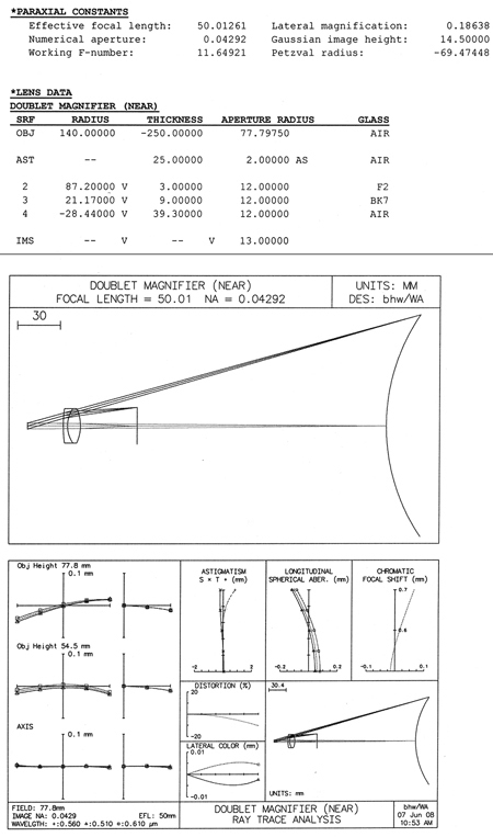
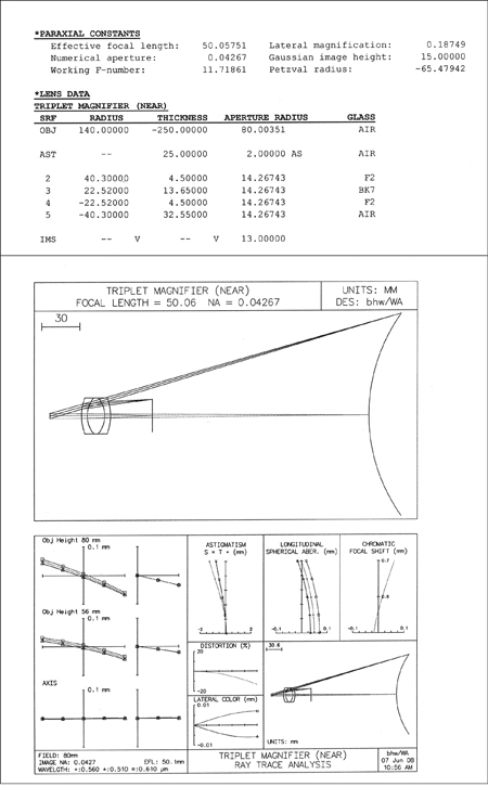
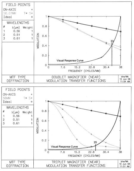
A typical 5× loupe, or magnifier, will most often take the form of a cemented doublet, or a symmetrical Hastings cemented triplet lens. We will evaluate typical designs in both of these forms to identify any significant performance differences between the two. The 50-mm doublet that was shown in Fig. 8.1 is more completely described, and its performance characteristics are shown in Fig. 8.2. Similar information has been generated for a second 5× loupe in the form of a Hastings triplet (see Fig. 8.3).
In the lens pictures in both figures the final image surface is the convex curved surface on the far right. The field curvature shown there (about 0.5 D) has been introduced for evaluation purposes. The aberration curves shown indicate that, while both lenses are very well corrected on axis, in this particular case the doublet actually appears to offer a slight advantage in off-axis performance over the Hastings triplet.
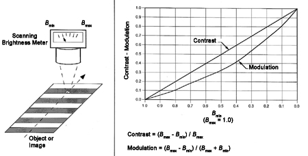
While these aberration curves do give some indication of lens performance, a more useful tool would be one that yields an absolute value for lens resolution when used with the eye. This is best accomplished by computing MTF for each lens. The MTF curve plots the modulation (contrast) of the image formed by the lens as a function of image frequency. Figure 8.4 illustrates the concept of modulation and contrast, showing how they might be measured and calculated. Assuming a pattern of parallel black and white stripes with a range of frequencies, the modulation or contrast of the object (or image) is arrived at by comparing the maximum and minimum brightness values as follows:
Modulation=(Bmax-Bmin)/(Bmax+Bmin)
Contrast=(Bmax-Bmin)/Bmax.
For MTF analysis, the object brightness from line to line is assumed to vary as a sine function. The modulation of a high contrast object is assumed to be 1.0 at all frequencies. At the image of that object, when the frequency is very low, the modulation will be close to 1.0. As the frequency at the image increases, the modulation of the image will decrease, i.e., the image will appear to be smeared as a result of diffraction effects and residual aberrations of the lens under test. Figure 8.5 shows the MTF curves for the two magnifier designs under consideration. That figure also contains a companion curve that is labeled "visual response curve." This curve indicates, for a typical visual system (eye) plus a 5.3× magnifier, the amount of image modulation that is required in order to visually resolve the corresponding frequency. While this typical visual response curve cannot be taken as absolute, it is valid for the relative comparison of two similar systems or designs. The point where this visual response curve crosses the MTF curve of the optics represents the maximum resolution possible when viewing a high contrast target with the 5.3× magnifier. Figure 8.5 shows that while both lenses are the same for on-axis imagery, for the off-axis case, the doublet will allow the viewer to resolve about 33 cycles/mm, while the triplet's off-axis resolution will fall to about 25 cycles/mm. axial travel per diopter = 282 / 1000 = 0.784 mm/D. Moving the eyepiece closer to the image being viewed will result in a diverging output beam, which corresponds to a negative diopter setting. To achieve the +3 to
—4 diopter focus range, the 28-mm eyepiece will have to be moved from
—3.2 to +2.4 mm relative to the infinity, or zero-diopter setting. The eyepiece focus design should provide a smooth, firm mechanism and an easily read scale indicating the approximate eyepiece diopter setting.
B. Walker, Optical Engineering Fundamentals, Second Edition, SPIE Press, Bellingham, WA (2008).
View SPIE terms of use.

