Optipedia • SPIE Press books opened for your reference.
Refractive Beam Expanders
Excerpt from Optical Design Fundamentals for Infrared Systems, Second Edition
The two basic configurations used for these afocal systems are the Galilean and the Keplerian telescope types, shown in Figs. 1 and 2.

Figure 1 Galilean beam expander.

Figure 2 Keplerian beam expander.
Since each of the two elements is suffering from spherical aberration, the exiting beam is not precisely collimated. The marginal ray converges under an angle γ. If each element is shaped individually for minimum spherical aberration, this convergence angle is

N is the index of refraction (both elements are from the same material). The magnification of the system m is expressed by the ratio of the exiting and entering beam diameters D and d. In Eq. (3.36), m is positive for the Galilean system. Because of the image reversal, it is negative for the Keplerian configuration. It is apparent that the convergence for the Galilean system is less than for the Keplerian, because the negative first element is afflicted with over-corrected spherical aberration, compensating somewhat for the larger amount of under-corrected spherical aberration from the positive second element. It will be noticed that the factor before the square bracket in Eq. (3.36) is twice the value of the minimum angular blur spot size for a single thin lens due to spherical aberration. The relative aperture f /# = fB/D =|fA|/D, and the separation of the elements t = fA + fB. For a germanium beam expander with N = 4, f /# = 2, m = 5, the convergence angles are γGal = −1.7 mrad, and γKep = −2.6 mrad.
The fact that a negative lens has over-corrected spherical aberration, as mentioned above, permits us to bend the negative entrance element of a Galilean beam expander in such a way that it will compensate completely for the under-corrected spherical aberration of the positive exit lens.
If the positive element B is shaped for minimum spherical aberration, its radii are


To compensate for the spherical aberration of this element, the proper shape of the negative element A can be extracted from the quadratic equation

m is the expansion ratio or magnification of the beam expander. It is expressed by
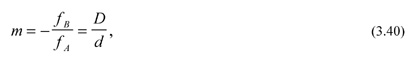
where D and d are the free aperture diameters of the elements, as indicated in Fig. 1. KA is the lens shape factor of element A. Rearranging an earlier given expression for the shape factor yields for the first radius of element A

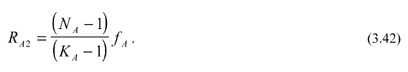
For the case when both elements are made from the same material, Eq.(3.39) reduces to

The table below lists the radii of four Galilean beam expanders using different materials for the elements. The focal length of element B was chosen to be 50 mm for all cases. The magnification of the systems is 5.
Radii in millimeters of Galilean beam expanders, corrected for spherical aberration.
| Material | N | KA | RA1 | RA2 | RB1 | RB2 |
| Glass | 1.5 | 1.81547 | −2.750 | −6.131 | +175.00 | −29.15 |
| Zinc Selenide | 2.4 | 3.18146 | −4.401 | −6.412 | −120.30 | −44.25 |
| Silicon | 3.4 | 4.69063 | −5.117 | −6.503 | −82.45 | −48.85 |
| Germanium | 4.0 | 5.58199 | −5.374 | −6.548 | −75.00 | −50.00 |
Optimizing the thin lens values with added thicknesses of 0.8 and 1.2 mm results in the arrangement shown in Fig. 3. In optimization, only the second and forth radii were modified in addition to the adjusted spacing between the elements. While the process was executed for a single wavelength—namely 10.6 μm—the CO2 laser wavelength, this beam expander performs well over the entire LWIR band from 8 to 12 μm.

Figure 3 Galilean 5× beam expander.
M. Riedl, Optical Design Fundamentals for Infrared Systems, Second Edition, SPIE Press, Bellingham, WA (2001).
View SPIE terms of use.

Non-Member: $58.00