Optipedia • SPIE Press books opened for your reference.
Signal-to-Noise Ratio
Excerpt from Optical Design Fundamentals for Infrared Systems, Second Edition
In its simplest form, the signal-noise-ratio is stated by
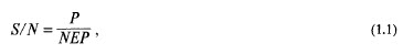
where P is the collected radiant power in watts that is received by the detector. NEP represents the noise equivalent power, a measure of the minimum signal that yields a unity signal-to-noise ratio.
The power can be calculated from
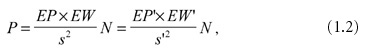
where EP and EW are the entrance pupil and entrance window areas (cm2) and s is the separation of the entrance window from the entrance pupil (cm). N is called the radiance of the source (W cm−2 ster−1). The primed symbols refer to the image side of the system. EP' and EW' are exit pupil and exit window and s' is the separation of the two.
In this fundamental expression, N appears equal in both relations, indicating that no reduction of radiation has been accounted for due to loss in transmission or other factors.
The principal point to be made is that Eq. (1.2) is an invariant. It provides a choice for determining the power transfer from either the object side (target side) or the image side (detector side).
When the object is located at infinity, the image is formed in the focal plane. In this case, the area of the exit pupil is D2π/4, and s' becomes f, which modifies the image-side expression of Eq. (1.2) to read
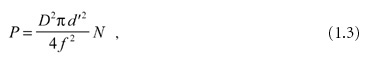
where d' is the linear dimension of the square detector. The detector is the exit window.
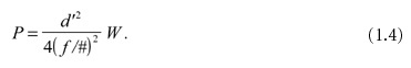
The radiated power in watts per square centimeter from a flat diffuse source surface into a hemisphere is the radiant emittance W. The relationship between the radiant emittance and the radiance is N = W/π.
With this and the substitution of f /# for f /D, Eq. (1.3) becomes
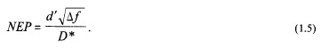
The noise equivalent power NEP is a function of the detector size d', the electrical bandwidth Δf used in the measurement, and the detector figure of merit D*, which has the somewhat unusual dimension of cm Hz1/2 W−1. D* is the signal-to-noise ratio when 1 W is incident on a detector having a sensitive area of 1 cm2, and the noise is measured with an electrical bandwidth of 1 Hz. So,
Substituting Eqs. (1.4) and (1.5) into Eq. (1.1) yields
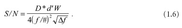
This simple expression indicates the strong influence of the chosen optical system. The S/N is inversely proportional to the square of f /#, the relative aperture. This means that an IR system with an f /1 objective performs four times better with regard to S/N than an f /2. Unfortunately, as we will see in Chapter 3, the “faster” (low f /#) a lens is, the larger the aberrations.
M. Riedl, Optical Design Fundamentals for Infrared Systems, Second Edition, SPIE Press, Bellingham, WA (2001).
View SPIE terms of use.

Non-Member: $58.00