Optipedia • SPIE Press books opened for your reference.
Phase-Shift Masks
Excerpt from Field Guide to Optical Lithography
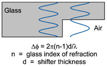 Phase-shift masks (PSMs) work by adding phase information to the mask in addition to amplitude information. A binary chrome-on-glass mask encodes the information about where to position resist edges using chrome (with zero amplitude transmittance) and glass (with 100% amplitude transmittance). A phase-shift mask relies on the fact that light passing through a transparent media will undergo a phase change as a function of its optical thickness, the refractive index times the physical thickness. Thus, light passing through a certain thickness of quartz will have a different phase transmittance than light passing through the same thickness of air. By adjusting the thickness of the quartz, any phase difference can be obtained.
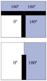
By setting the phase shift to be 180°, high-resolution imaging with good depth of focus can be obtained. Light from shifted and unshifted parts of the mask, when combined, will interfere and cancel out at the image plane due to the 180° phase shift. If the shifted and unshifted light is of equal quantity the cancellation will be complete. 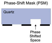 A 0–180° phase edge on a mask will print as a narrow dark line. An array of these edges will print patterns of lines and spaces with widths as low as 0.25λ/NA. Common types of PSMs are alternating (pictured here) and attenuated PSMs. Practical implementation of PSMs is limited by phase termination problems and mask fabrication difficulties.
Alternating Phase-Shift Masks
Alternating phase-shift masks (AltPSM) are used to print narrow lines in positive photoresist by making the clear areas on either side of the line of opposite phase. Thus, the phase cancellation effect of light diffracted from either side of the line will keep the line dark and narrow, even when out of focus. AltPSM is a “strong” PSM that can maximize resolution and depth of focus.
AltPSM suffers from two very important drawbacks. On the mask fabrication side, a subtractive etch to create the phase-shifted space results in reduced amplitude transmittance and non-perfect 180° phase transmittance, both of which vary with the width of the shifted space. Biasing the etched spaces wider and allowing the etch to undercut the chrome can alleviate but not eliminate the problem.
 The second difficulty is called the phase conflict problem. Attempting to phase shift an arbitrary layout of lines will invariably lead to phase conflicts: no phase shift where you do want it, and a phase shift where you don’t want it. The first type results in a lack of phase shift across a critical feature when there is an odd wrapping of phase assignments. This “nonshifted” feature will not properly print. The second type is also called the termination problem since it usually occurs at the end of a line. Alternating phase across each side of a line will result in those two phases meeting at the line end. Whenever two opposing phases meet, a dark interference line is created causing an unwanted resist line to print. Generally, a second “trim” exposure is required to remove unwanted phase prints.
Attenuated Phase-Shift Masks
Attenuated phase-shift masks (also called the embedded phase-shift masks, or EPSM) have been very widely adopted for contact hole and via printing, and are becoming fairly mainstream for other critical lithography layers as well. This type of PSM is generally called a “weak” shifter—it provides only a portion of the full resolution and depth of focus potential of alternating PSM. Its great advantage is the simplicity and low cost of replacing chrome on glass (COG) masks, the non-phase shift alternative. Essentially, an existing design based on COG can be converted to an EPSM by simply recalibrating the optical proximity correction (OPC) models used to apply OPC to the design. Mask manufacturing, while certainly more difficult than COG, is not dramatically different (the chrome is replaced by a more complex absorber such as molybdenum silicon) and only somewhat more costly. In short, the transition from COG to EPSM-based lithography presents no major hurdles.
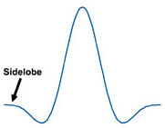 Typical EPSM materials have 6% intensity transmittance and a 180° phase shift, though higher transmittance masks are sometimes used. The resulting 0–180° phase edge makes the aerial image edges steeper and better defined. The overall background transmittance of 6% can cause problems when nearby features interact constructively to produce sidelobes, unwanted regions of high intensity. If the intensity in the sidelobe becomes too high, it could print as an unwanted hole in the photoresist.
While EPSM on its own does not provide the resolution and depth of focus enhancement that can come with AltPSM, the combination of EPSM with off-axis illumination can be optimized to give very good results.
C. A. Mack, Field Guide to Optical Lithography, SPIE Press, Bellingham, WA (2006).
View SPIE terms of use.
